G30LD ESC modifications

4 April 2022
4
0
E-Scooter
Ninebot Max
Hello!
What is the best mosfet available for this controller? What type is used?
Which resistor/resistors should you change when overvolting? Where is it located on the board?
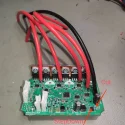
IMG_20220416_235823.webp
 
Hi,

1.
The Flipsky 75100 (Vesc Clone) uses 6* MDP10N027 MosFETs and it is rated to 20S and 100A, so maybe a very good choice if available.
You have to solder the traces stronger too!
2.
If the battery voltage is above 60V you have to do a trace cut to the first step down and supply it with a voltage below 60V. No, I don't know the exact location. I think it should be near the capacitor in the next picture.
3.
You have to change the resistor of the battery voltage divider to get a voltage at the output below 3V3 at full battery. No, I don't know the position. This should be the right, but I didn't test it:
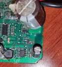
IMG_20220417_010507.jpg
12D (120.000k) and 10k is about 43V.
27D (270.000k) and 10 will give about 92 V.
You habe to setup the ADC Value in the firmware!
4.
You have to change the big capacitors, but it looks, you're always doing this.

If you find a solution for 2&3 please give me a short feedback, I would like to have this information for my knowledge. Thanks!
 
Zuletzt bearbeitet:
  • Hilfreich!
Reaktionen: Gerhard
Thank you for replying.
I think i found the resistor. It's in a similar location on the G30LD board. I measured it and it seems right. I thought that the resistor was changed instead of cutting the trace? Do i have to both cut the trace and change the resistor in order to run over 60v?
resistor01.webp
 
Don't think so for the Cut.
IMG_20220417_163854.jpg
I think, it should be there.
Take a Multimeter and messure the voltage at the smal ceramic capacitors in front of the elekrolyt capacitor and pin2 of the ic. Take a look for the typ and the datasheet for knowing, if this ist the Input.
So the Cut should be made in front of the Elko, If I'm right, but bether connect the Elko back to the input.

Or Cut the large trace behind the Elko and leave the resistor, but then you messure the 10S voltage.
 
  • Hilfreich!
Reaktionen: DeepSocketSet
Thank you!! I took this picture of the chip. I dont find any data sheet on it. Once i get the capacitors i ordered and installed them, i will hook the controller up to my labpsu and measure as instructed. I aslo ordered this 33uF 100v cap to replace the one in the picture if needed.
ic.webp
 
Don't know the type also, only read max. 60V Input.
But I think, Pin 2 is the input. The Cs und the R are also connect, so check If you can cut in front of (logical / optical behind 😉) the Elko.
 
  • Hilfreich!
Reaktionen: DeepSocketSet
Thank you!! I took this picture of the chip. I dont find any data sheet on it. Once i get the capacitors i ordered and installed them, i will hook the controller up to my labpsu and measure as instructed. I aslo ordered this 33uF 100v cap to replace the one in the picture if needed.Anhang anzeigen 16371
You can change this voltage regulator to the SY8501 instead of cutting the trace as the voltage input range is greater (7V - 100V).

What capacitors did you use to fit the ESC in the standard case?