


Da ich nicht Deutsch als native sprache habe und es hier ein sehr langes bericht betrifft und auch fur die nicht Deutscher sehr interesant ist, habe ich dieser tutorial komplett auf Englisch gemacht.
This whole project is Open source and has an according license to it:

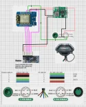
WARNING!!!!!! There are 5 PIN cables / connectors that don't follow the regular color coding(!)
Color coding used by the cables i used and thus correct:

So check your cables and if required use different colors as in my examples.

Hello all,
As I own myself an Ninebot GT2 but live in a country where we have an enforced speed regulation and this is often checked by the Police I was shitting in my pants driving around with my Ninebot GT2.
Since the Ninebot GT2 has no custom firmware and the speed set at it will always stay like that and not easy (read: Quick / Hidden) to revert to the speed regulations.
As we all know there is the thing called chip tuning with overpriced chips for various scooters and that was exact my idea to make with one thing in mind: The cost should be as low as possible and not ending up at these chip sellers that rip you off financially (they go as high as 100$/Euro(!)) for something that contains just 6 $/Euro of hardware.
So this is why I do it on the open concept and give you the chance to build it yourself. Of course if you cant build it yourself I will give the option to buy it but I am 100% transparent about the costs and anyone charging you more then this price is just ripping you off.
So now back to the “Chip” what does it do ……
It is very simple it sets when you power on the scooter (GT series) all speeds to 22Km/h for all modes so whatever happens the scooter follows the speed regulation. (Other speeds can be requested)
Now you have 2 options to set a higher speed where 1: Using the original Ninebot app with the speed sliders and 2: The Chip provides also an access point that you can connect with your mobile and gives your a web-interface to select or use the sliders for the desired speed.

Also there is a page to update the firmware if any new option arrives.
In the following video you see the device in action. I used on purpose 2 phones so you can easy see what is done and what is happening. After any command the taillight will blink shortly to confirm command received. [Video follows still have to make it .....]
For now i put the old video here as it shows roughly what happens .....
So what do you need or better said what would it cost …..
All depends on where you buy your stuff but for the easy thing I keep Aliexpress as reference but if you might have quicker / other sources.
Required hardware:
- ESP8266 Wemos D1 Mini ( 3,50 Euro )( https://s.click.aliexpress.com/e/_DFIK0dB )
- 12V to 5V BUC Converter ( 2,30 Euro ) ( https://s.click.aliexpress.com/e/_DFYR9m9 ) (Use 3A Adjustable)
- 5 Pin Juliet cable male + female plug ( 4,80 Euro) ( https://www.aliexpress.com/item/1005004114774183.html )
- An 3D printed case ( 0,00 Euro ) (
As you see the total hardware costs are about 11 $/Euro without the case so means if anyone would be selling this and charge you more then 20 $/Euro you pay too much.
So now the real deal …. flashing the ESP and wire it all up and download the required .bin file here:
First of all flash the right .bin file on the ESP8266. This can be done with for example ESPEasy what can be downloaded at

Now when the ESP8266 restarts you will see an Wifi Network called “NineNot-GT” take your mobile phone and connect this and give as password: 12345678
If you phone tells you that this connection has no internet but still want to use it say yes and tick any remember option if shown.
It’s time to open the browser and type in the address 192.168.4.1 this will open a simple page as shown here.
In general you wont need this page unless you don’t see the speed sliders in the original Ninebot app. But of course feel free to use it when needed to set a different speed. Keep in mind the sliders don’t show the actual values set by an other app so if you set 70Km/h in the Ninebot app the sliders will still show 22Km/h.
There is an additional page available but this is to update the firmware of the ESP8266 and here you can upload any newer version I would release. The update page can be found at 192.168.4.1/update please only use the Firmware option (!)

As said in general you don’t have to do anything since at boot the device set all your speeds of Eco / Sport / Race to 22Km/h and further you use the Ninebot app or the Webinterface to set a speed.
Any speed setting is confirmed with a short flash of the taillight.
Now it’s up to cabling and put the ESP8266 in the case with the BUC together.
First solder 3 wires to the ESP8266 we use 5V (Red), Ground (Black) and Data (Green)
The green wire comes at the D4 pin of the ESP8266
Now you can hotglue the ESP8266 into its case

Now solder 2 different Black & Red wire on the input side of your buck and connect it to a 12V power supply (don’t connect the output yet as we have to adjust the output voltage). Take a Multimeter and measure the output voltage if needed adjust this to 5V and when done take a bit of nail polish to ensure the trimmer wont be moving in a later stage.

Time to connect the Red & Black from the ESP8266 to the Buc output +-
Then take the 5 P Juliet cable and cut 10cm before the connector and strip the outer hull off for about 4-5 cm.

Put both ends into the case I prefer to have the USB connector up for later purpose and thus the Female connector comes on that side. On the other side we insert the Male connector and we strip all strands.
From the Juliet cable we need only 3 wires the other 2 have just to be connected together again so we connect blue+blue and yellow+yellow again (use shrink tube) and we have the Green, Red and Black left. As you can guess the All the reds come together (the red from Buc input), all the blacks come together (the black from Buc input) and all the greens come together (the green from the ESP)

This is the moment supreme as now you going to add it to the Scooter and thus remove the upper port of the steering pole by removing the 6 screws. Now pull gently the cable out and disconnect the Juliet connect the box in between.
If you now turn on the scooter you will see in about 5 seconds a short flash of the back light. This means all speeds have been set to 22Km/h. When you control via the Web interface any command or speed setting will let the back light flash short as confirmation.
When you power off the scooter these speeds stay and will be reset again at startup. When you power cycle the scooter give it a few seconds to fully turn off since the 12V line keeps power for about 10 seconds and then shuts off.
[Update 4 Feb]
RF Remote version .... as there was a request how to do it without grabbing the phone i worked on a version that uses a RF Remote.
With this remote you can now: Lock, Unlock, No Limit and Speed Limit mode easy activate.
Parts needed:
ESP8266: https://www.aliexpress.com/item/1005006217202852.html
BUC: https://s.click.aliexpress.com/e/_DlaO6Wp (use the 3A Adjustable and set it to 5V)
Cable: https://www.aliexpress.com/item/1005004114774183.html (See waring about cables this specific one uses the color scheme on the right side)
RF Remote: https://s.click.aliexpress.com/e/_DBzJj8p
Wire diagram: (Updated 07-Feb)

A video of all in action:
[Update 5 Feb]
GT1(D) Information .... The first tests with the GT1 has been done currently it is not possible on a easy way to change the serial of the GT1D as the serial changing routine is locked and thus can only be changed with ST-Link (Tutorial / Testing is work in progress). For the regular GT1 series the chip also works if 2 conditions are met:
1: Is has the serial prefix of S1GCA (China)
2: It has the firmware / app that shows the speed sliders as only that firmware allows speed changes
Further there is then no difference and no special version of the chip is required as the speed register of GT1 & GT2 are exact the same.
[Update 8 Feb]
The kinda Manual of how to control it can be found in the Google drive link.
If you have any questions pleas just reach out to me on Telegram: https://t.me/St0fzuiger or via Discord: pinky_narf
Thanks,
Pinky aka St0fzuiger
This whole project is Open source and has an according license to it:
Um Links zu sehen, melde dich bitte an
WARNING!!!!!! There are 5 PIN cables / connectors that don't follow the regular color coding(!)
Color coding used by the cables i used and thus correct:
So check your cables and if required use different colors as in my examples.
Hello all,
As I own myself an Ninebot GT2 but live in a country where we have an enforced speed regulation and this is often checked by the Police I was shitting in my pants driving around with my Ninebot GT2.
Since the Ninebot GT2 has no custom firmware and the speed set at it will always stay like that and not easy (read: Quick / Hidden) to revert to the speed regulations.
As we all know there is the thing called chip tuning with overpriced chips for various scooters and that was exact my idea to make with one thing in mind: The cost should be as low as possible and not ending up at these chip sellers that rip you off financially (they go as high as 100$/Euro(!)) for something that contains just 6 $/Euro of hardware.
So this is why I do it on the open concept and give you the chance to build it yourself. Of course if you cant build it yourself I will give the option to buy it but I am 100% transparent about the costs and anyone charging you more then this price is just ripping you off.
So now back to the “Chip” what does it do ……
It is very simple it sets when you power on the scooter (GT series) all speeds to 22Km/h for all modes so whatever happens the scooter follows the speed regulation. (Other speeds can be requested)
Now you have 2 options to set a higher speed where 1: Using the original Ninebot app with the speed sliders and 2: The Chip provides also an access point that you can connect with your mobile and gives your a web-interface to select or use the sliders for the desired speed.
Also there is a page to update the firmware if any new option arrives.
In the following video you see the device in action. I used on purpose 2 phones so you can easy see what is done and what is happening. After any command the taillight will blink shortly to confirm command received. [Video follows still have to make it .....]
For now i put the old video here as it shows roughly what happens .....
So what do you need or better said what would it cost …..
All depends on where you buy your stuff but for the easy thing I keep Aliexpress as reference but if you might have quicker / other sources.
Required hardware:
- ESP8266 Wemos D1 Mini ( 3,50 Euro )( https://s.click.aliexpress.com/e/_DFIK0dB )
- 12V to 5V BUC Converter ( 2,30 Euro ) ( https://s.click.aliexpress.com/e/_DFYR9m9 ) (Use 3A Adjustable)
- 5 Pin Juliet cable male + female plug ( 4,80 Euro) ( https://www.aliexpress.com/item/1005004114774183.html )
- An 3D printed case ( 0,00 Euro ) (
Um Links zu sehen, melde dich bitte an
)As you see the total hardware costs are about 11 $/Euro without the case so means if anyone would be selling this and charge you more then 20 $/Euro you pay too much.
So now the real deal …. flashing the ESP and wire it all up and download the required .bin file here:
Um Links zu sehen, melde dich bitte an
First of all flash the right .bin file on the ESP8266. This can be done with for example ESPEasy what can be downloaded at
Um Links zu sehen, melde dich bitte an
make sure when you start the application you place the .bin file into the /bin directory of ESPEasy (this directory will be created after starting ESPEasy). Connect your ESP to your PC hit the reload button within ESPEasy and select the right serial port. Then select the .bin file from the drop-down. And press flash (no further settings requiredNow when the ESP8266 restarts you will see an Wifi Network called “NineNot-GT” take your mobile phone and connect this and give as password: 12345678
If you phone tells you that this connection has no internet but still want to use it say yes and tick any remember option if shown.
It’s time to open the browser and type in the address 192.168.4.1 this will open a simple page as shown here.
In general you wont need this page unless you don’t see the speed sliders in the original Ninebot app. But of course feel free to use it when needed to set a different speed. Keep in mind the sliders don’t show the actual values set by an other app so if you set 70Km/h in the Ninebot app the sliders will still show 22Km/h.
There is an additional page available but this is to update the firmware of the ESP8266 and here you can upload any newer version I would release. The update page can be found at 192.168.4.1/update please only use the Firmware option (!)
As said in general you don’t have to do anything since at boot the device set all your speeds of Eco / Sport / Race to 22Km/h and further you use the Ninebot app or the Webinterface to set a speed.
Any speed setting is confirmed with a short flash of the taillight.
Now it’s up to cabling and put the ESP8266 in the case with the BUC together.
First solder 3 wires to the ESP8266 we use 5V (Red), Ground (Black) and Data (Green)
The green wire comes at the D4 pin of the ESP8266
Now you can hotglue the ESP8266 into its case
Now solder 2 different Black & Red wire on the input side of your buck and connect it to a 12V power supply (don’t connect the output yet as we have to adjust the output voltage). Take a Multimeter and measure the output voltage if needed adjust this to 5V and when done take a bit of nail polish to ensure the trimmer wont be moving in a later stage.
Time to connect the Red & Black from the ESP8266 to the Buc output +-
Then take the 5 P Juliet cable and cut 10cm before the connector and strip the outer hull off for about 4-5 cm.
Put both ends into the case I prefer to have the USB connector up for later purpose and thus the Female connector comes on that side. On the other side we insert the Male connector and we strip all strands.
From the Juliet cable we need only 3 wires the other 2 have just to be connected together again so we connect blue+blue and yellow+yellow again (use shrink tube) and we have the Green, Red and Black left. As you can guess the All the reds come together (the red from Buc input), all the blacks come together (the black from Buc input) and all the greens come together (the green from the ESP)
This is the moment supreme as now you going to add it to the Scooter and thus remove the upper port of the steering pole by removing the 6 screws. Now pull gently the cable out and disconnect the Juliet connect the box in between.
If you now turn on the scooter you will see in about 5 seconds a short flash of the back light. This means all speeds have been set to 22Km/h. When you control via the Web interface any command or speed setting will let the back light flash short as confirmation.
When you power off the scooter these speeds stay and will be reset again at startup. When you power cycle the scooter give it a few seconds to fully turn off since the 12V line keeps power for about 10 seconds and then shuts off.
[Update 4 Feb]
RF Remote version .... as there was a request how to do it without grabbing the phone i worked on a version that uses a RF Remote.
With this remote you can now: Lock, Unlock, No Limit and Speed Limit mode easy activate.
Um Links zu sehen, melde dich bitte an
Parts needed:
ESP8266: https://www.aliexpress.com/item/1005006217202852.html
BUC: https://s.click.aliexpress.com/e/_DlaO6Wp (use the 3A Adjustable and set it to 5V)
Cable: https://www.aliexpress.com/item/1005004114774183.html (See waring about cables this specific one uses the color scheme on the right side)
RF Remote: https://s.click.aliexpress.com/e/_DBzJj8p
Wire diagram: (Updated 07-Feb)
A video of all in action:
[Update 5 Feb]
GT1(D) Information .... The first tests with the GT1 has been done currently it is not possible on a easy way to change the serial of the GT1D as the serial changing routine is locked and thus can only be changed with ST-Link (Tutorial / Testing is work in progress). For the regular GT1 series the chip also works if 2 conditions are met:
1: Is has the serial prefix of S1GCA (China)
2: It has the firmware / app that shows the speed sliders as only that firmware allows speed changes
Further there is then no difference and no special version of the chip is required as the speed register of GT1 & GT2 are exact the same.
[Update 8 Feb]
The kinda Manual of how to control it can be found in the Google drive link.
If you have any questions pleas just reach out to me on Telegram: https://t.me/St0fzuiger or via Discord: pinky_narf
Thanks,
Pinky aka St0fzuiger
Anhänge

Zuletzt bearbeitet:
")


 . Kurze Frage: Buck input =12V?
")
