RP ✔️ Speedlimiter & "German Maneuver" selber bauen

S1m0n

Content-Creator
12 Juli 2021
900
874
E-Scooter
Pro2/g30/Legend
Hier möchte ich euch eine einfache und kostengünstige Möglichkeit vorstellen, eine Drossel auf 22kmh selber zu bauen, nachdem das 1k Kit verbaut oder der IO Hawk Controller geboostet wurde
Funktioniert übrigens auch mit Ninebot G30d, Xiaomi 1S, Pro2 (getestet) und allen anderen Scootern, die als Signalgeber einen linearen Hallsensor benutzen (in den meisten Fällen ist es ein 49E)

Zu diesem Beitrag auch bitte den Haftungsausschluss der Nutzungsbedingungen - Pkt.8 beachten!

Benötigt wird:
1x 20k Potentiometer
1x 12V Funk-Relais (Fernbedienung am besten mit 2 Buttons, aber keine Pflicht)
1x 48V→ 12V Stepdown
Ein paar Käbelchen/Stecker, Schrumpfschlauch, Lötkolben
1x XH 2.54 8Pin Stecker/Buchse (für Plug & Play am Smarthub)
Vorweg:
In meinem Bespiel ist:
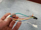
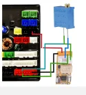
- das rote Kabel der Poti (Drossel)
- das grüne Kabel das Signal
- das weissen Kabel entdrosselt


Als erstes löten wir an den Pin 1&2 vom Potentiometer jeweils ein Kabel
IMG_20220409_135336.jpg


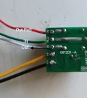
Als nächstes Nächstes nehmen wir das Realis und stecken es wie folgt zusammen:
V- = 12V- vom Stepdown Modul
V+ = 12V+ vom Stepdown Modul
Weisse Kabel = NO (entdrosselt)
grüne Kabel = COM
rote Kabel = NC (Drossel)
IMG_20220409_135421.jpg


Das Ganze sollte dann so aussehen:
IMG_20220409_135503.jpg


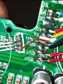
Danach schneidet man das grüne Kabel vom Display durch, am Controller.
Ein Ende verbindet man mit dem grünen Kabel (COM am Relais)
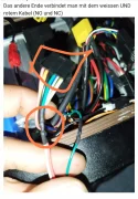
Das andere Ende verbindet man mit dem weissen UND rotem Kabel (NO und NC)
IMG_20220409_135617.jpg


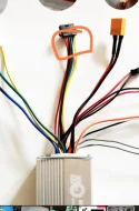
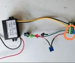
Zu guter Letzt schliesst man noch den Stepdown Converter an...
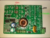
+ An irgendein oranges Kabel (48V+), was vom Controller kommt
- An irgendein schwarzes Kabel (48V-), was vom Controller kommt

Wenn der Scooter jetzt aus ist, angeschaltet wird und das Relais mit Strom versorgt wird, schaltet es automatisch immer auf die Drossel (NC = normaly closed)
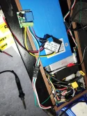
Proof of Concept ↓


Edit:
Tiny Funk Relais Modul (ohne Fernbedienung): https://a.aliexpress.com/_mKkHUwc
Macht den Limiter kleiner wie ein Feuerzeug 🔥
IMG_20220904_164749.jpg
 

Anhänge

  • IMG_20220409_135809.webp
    IMG_20220409_135809.webp
    214,1 KB · Aufrufe: 201
  • IMG_20220904_145803.webp
    IMG_20220904_145803.webp
    164,7 KB · Aufrufe: 166
  • IMG_20220904_194121.webp
    IMG_20220904_194121.webp
    109,9 KB · Aufrufe: 148
  • IMG_20220904_194136.webp
    IMG_20220904_194136.webp
    102,3 KB · Aufrufe: 162
  • IMG_20221010_142419.webp
    IMG_20221010_142419.webp
    60,9 KB · Aufrufe: 160
Zuletzt bearbeitet von einem Moderator:
Dem Speedcontroller macht es nichts aus, wenn das digitale Gassignal nicht dem Analogen entspricht? Oder nur innerhalb einer gewissen Toleranz? Ich hatte zuletzt vermutet, dass ein GM auf diese Weise nicht klappen könne.
 

Das Gas wird nochmal digital als Zahlenwert von ca. 40-180 gesendet.
 
Legend bzw. SmartHub Nutzer, mit dem 1k Kit, können auch das dieses grüne Kabel von Adapterkabel durchtrennen ↓
 

Anhänge

  • IMG_20220410_134142.webp
    IMG_20220410_134142.webp
    77,4 KB · Aufrufe: 216
  • Liebe zum Detail! (2 Punkte)
  • Hilfreich!
Reaktionen: SeBi1896 und Dr.One
Hi.
I have a Kaabo Mantis 8 pro+ with Minimotors Controller and display.
Here I have a single gray wire that's used for speed limiter.
I have installed a buck converter (https://www.ebay.de/itm/402379275385)
and a wireless relay module (https://www.amazon.de/dp/B081CD9GHD/)

Would i connect the speedlimiter wire to the potentiometer, like speedlimiter wire - potentiometer - speedlimiter?

I need to do something, cause when the speedlimiter is connected the scoot runs at 30kmph and the legal speed is 20kmph
 
where does the gray wire go? to the controller? then no. you have to open your display and see which cable is directly connected to the throttle. or take a picture Stein Stein
 

Anhänge

  • IMG_20220807_175802.webp
    IMG_20220807_175802.webp
    188,3 KB · Aufrufe: 157
Yeah, the gray wire is connected to the controller. There is a connection hub as well on the Minimotors Controller, not sure if that would help.
898028867-436608559.webp

Hd8811b8387ff465bafae7df889fdfbbeX.webp
 
Yeah, the gray wire is connected to the controller
No, this does not work with the potentiometer. I think with you it is also the green cable, at the plug of the display. The potentiometer must be connected to it, together with the relay. The gray cable is then simply left open. If you then confirm the relay, the gas signal runs either over the potentiometer (locked 20kmh) or the direct way (unlocked).
 

Anhänge

  • IMG_20220807_210817.webp
    IMG_20220807_210817.webp
    124 KB · Aufrufe: 119
  • IMG_20220807_210842.webp
    IMG_20220807_210842.webp
    71,1 KB · Aufrufe: 125
  • Hilfreich!
Reaktionen: Dr.One
Ohh so I need a wire from the green cable on the controller, over to the potentiometer and then in to the relay?

So buck converter to relay, then from relay to potentiometer and over to the green cable and also connect the gray cable to relay as well?
 
Ohh so I need a wire from the green cable on the controller, over to the potentiometer and then in to the relay?
Yes
and also connect the gray cable to relay as well?
No

You have to cut the green cable. Then you plug one end into "COM" at the relay ... that is the input. Then you make the potentiometer at "NC" (=normally close) - that means whenever the scooter starts, first the is locked (20kmh). Then you make another cable at "NO" (normally open) - that is unlocked. NC / NO are outputs... either / Or. Both outputs you connect to the other end of the green cable, which you cut off.
You don't need the grey cable anymore
 

Anhänge

  • IMG_20220807_221854.webp
    IMG_20220807_221854.webp
    40,9 KB · Aufrufe: 156
  • IMG_20220807_221600.webp
    IMG_20220807_221600.webp
    46,8 KB · Aufrufe: 137
  • Hilfreich!
Reaktionen: Dr.One
I'll give that a try. Thanks mate
U Welcome
But better you check first whether the assumption is correct, not that the assignment is different and something is broken. If you have cut the green cable, test whether the scooter still accepts gas. If yes or if errros come, it will be the wrong one. Better double check
 
  • Hilfreich!
Reaktionen: Dr.One
S1m0n,
interessante Schaltung machst du da. Habe für ein Legend meiner Frau die TuneUp-Box gekauft und deine Schaltungen haben mich inspiriert für mein Legend (mit SmartHub, kein Kit) eine solche/ähnliche Schaltung selbst zu bauen. Ich habe ein 433 MHz Universal-Fernschalter-Sender DC 12 V, ähnlich dem auf dem Foto neben Feuerzeug (links mit Aufschrift "UART 2") mit nur 4 Kabel. Am SmartHub ist ein Step Down nicht nötig, richtig? und wie würde der Anschluss mit 4 Kabel auf dem Foto ..._142419.jpg aussehen?
Tiny Funk Relais Modul mit Fernbedienung: https://www.ebay.de/itm/354279850795?var=623667311609
Den 20k Poti habe ich auch.
 
Nein, die von dir geschickten Links funktionieren nicht. Das sind Funk Schalter, keine Funk Realis.
Ein Realis hat immer fünf Kabel (NC COM NO V+ und V-/GND)
Ansonsten ist es korrekt das man beim Smarthub kein step-down braucht.
Ich habe die die Punkte beim smarthub makiert..
12V+ gibt's beim unten Pin von 7&11 Port
GND kannst du vom 2te Pin von oben beim Display Port nehmen.
Das Gas Signal ist der 6te Pin von oben beim Dispaly Port

Uart 2 hat mit alledem nichts zu tun. Das ist ein Kabelstrang von einem anderem anderen Controller
J joj
 

Anhänge

  • IMG_20221023_181346.webp
    IMG_20221023_181346.webp
    108,9 KB · Aufrufe: 135
  • Liebe zum Detail! (2 Punkte)
Reaktionen: Dr.One
Schnell und deutlich. Und ich habe mir vorher den Kopf zerbrochen, wie das mit den 4 Kabeln funktionieren soll :)
Die TuneUp-Box wird zB nur über den Stecker 3 im SmartHub versorgt. Wollte die schon öffnen. So brauche ich das nicht. Danke.