

RP ✔️ Speedlimiter & "German Maneuver" selber bauen
- Ersteller S1m0n
- Erstellt am
-
- Schlagworte
- #iohwk #ninenot #tunig 22kmh german maneuver speedlimiter xiamoi

Du verwendest einen veralteten Browser. Es ist möglich, dass diese oder andere Websites nicht korrekt angezeigt werden.
Du solltest ein Upgrade durchführen oder einen alternativen Browser verwenden.
Du solltest ein Upgrade durchführen oder einen alternativen Browser verwenden.
- 12 Juli 2021
- 887
- 861
- E-Scooter
- Pro2/g30/Legend
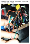
No, this does not work with the potentiometer. I think with you it is also the green cable, at the plug of the display. The potentiometer must be connected to it, together with the relay. The gray cable is then simply left open. If you then confirm the relay, the gas signal runs either over the potentiometer (locked 20kmh) or the direct way (unlocked).Yeah, the gray wire is connected to the controller
Anhänge

- 7 August 2022
- 4
- 0
- E-Scooter
- Kaabo mantis 8pro+
Ohh so I need a wire from the green cable on the controller, over to the potentiometer and then in to the relay?
So buck converter to relay, then from relay to potentiometer and over to the green cable and also connect the gray cable to relay as well?
So buck converter to relay, then from relay to potentiometer and over to the green cable and also connect the gray cable to relay as well?
- 12 Juli 2021
- 887
- 861
- E-Scooter
- Pro2/g30/Legend
YesOhh so I need a wire from the green cable on the controller, over to the potentiometer and then in to the relay?
Noand also connect the gray cable to relay as well?
You have to cut the green cable. Then you plug one end into "COM" at the relay ... that is the input. Then you make the potentiometer at "NC" (=normally close) - that means whenever the scooter starts, first the is locked (20kmh). Then you make another cable at "NO" (normally open) - that is unlocked. NC / NO are outputs... either / Or. Both outputs you connect to the other end of the green cable, which you cut off.
You don't need the grey cable anymore
Anhänge


- 12 Juli 2021
- 887
- 861
- E-Scooter
- Pro2/g30/Legend
U WelcomeI'll give that a try. Thanks mate
But better you check first whether the assumption is correct, not that the assignment is different and something is broken. If you have cut the green cable, test whether the scooter still accepts gas. If yes or if errros come, it will be the wrong one. Better double check

S1m0n,
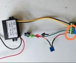
interessante Schaltung machst du da. Habe für ein Legend meiner Frau die TuneUp-Box gekauft und deine Schaltungen haben mich inspiriert für mein Legend (mit SmartHub, kein Kit) eine solche/ähnliche Schaltung selbst zu bauen. Ich habe ein
Tiny Funk Relais Modul mit Fernbedienung:
Den 20k Poti habe ich auch.
interessante Schaltung machst du da. Habe für ein Legend meiner Frau die TuneUp-Box gekauft und deine Schaltungen haben mich inspiriert für mein Legend (mit SmartHub, kein Kit) eine solche/ähnliche Schaltung selbst zu bauen. Ich habe ein
Um Links zu sehen, melde dich bitte an
, ähnlich dem auf dem Foto neben Feuerzeug (links mit Aufschrift "UART 2") mit nur 4 Kabel. Am SmartHub ist ein Step Down nicht nötig, richtig? und wie würde der Anschluss mit 4 Kabel auf dem Foto ..._142419.jpg aussehen?Tiny Funk Relais Modul mit Fernbedienung:
Um Links zu sehen, melde dich bitte an
Den 20k Poti habe ich auch.
- 12 Juli 2021
- 887
- 861
- E-Scooter
- Pro2/g30/Legend
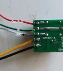
Nein, die von dir geschickten Links funktionieren nicht. Das sind Funk Schalter, keine Funk Realis.
Ein Realis hat immer fünf Kabel (NC COM NO V+ und V-/GND)
Ansonsten ist es korrekt das man beim Smarthub kein step-down braucht.
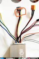
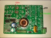
Ich habe die die Punkte beim smarthub makiert..
12V+ gibt's beim unten Pin von 7&11 Port
GND kannst du vom 2te Pin von oben beim Display Port nehmen.
Das Gas Signal ist der 6te Pin von oben beim Dispaly Port
Uart 2 hat mit alledem nichts zu tun. Das ist ein Kabelstrang von einem anderem anderen Controller
J joj
Ein Realis hat immer fünf Kabel (NC COM NO V+ und V-/GND)
Ansonsten ist es korrekt das man beim Smarthub kein step-down braucht.
Ich habe die die Punkte beim smarthub makiert..
12V+ gibt's beim unten Pin von 7&11 Port
GND kannst du vom 2te Pin von oben beim Display Port nehmen.
Das Gas Signal ist der 6te Pin von oben beim Dispaly Port
Uart 2 hat mit alledem nichts zu tun. Das ist ein Kabelstrang von einem anderem anderen Controller
J joj
Anhänge
")
")
-
Unsere Webseite verwendet nur technisch notwendige Cookies. Diese helfen dabei, Inhalte anzupassen und deine Anmeldung nach dem Login zu speichern. Durch die weitere Nutzung unserer Webseite erklärst du dich damit einverstanden.